
Computational Fluid Dynamics (CFD)
Independent CFD engineering support for oil & gas, offshore, energy and industrial applications
Middle East · Netherlands · Europe · North America
Computational Fluid Dynamics (CFD) helps engineers understand how fluids, gases and heat behave before equipment is built, modified or put into operation.
Auryx Energy coordinates independent CFD studies for oil & gas operators, OEMs, EPC contractors and industrial companies in the Netherlands and internationally. Our CFD capability covers fluid flow, combustion, heat transfer, multiphase flow, dispersion, aerodynamics, hydrodynamics and fluid-structure interaction.
Each study is built around a specific engineering question, with the objective of producing results that support a design, operational or investment decision, not simply another technical report.
CFD for engineering decisions
CFD can be applied throughout the project lifecycle. It can be used during concept development, to compare design alternatives, during detailed engineering, to validate or optimize equipment, and on existing installations to investigate underperformance, operational problems or proposed modifications.
Simulation is particularly valuable where physical measurement is difficult. Instead of relying only on measurements at accessible sensor locations, CFD provides a detailed view of pressure, velocity, temperature and species concentration throughout the modelled domain. This can help answer not only what is happening, but why it is happening.
CFD also complements physical testing and field measurements. Where validation data is available, it can be used to strengthen the model and reduce unnecessary test iterations.
CFD applications & simulation examples
Transient combustion simulation of an industrial natural gas burner
Natural Gas Burner
CFD can be used to investigate fuel-air mixing, combustion behaviour, temperature distribution and burner performance across different operating conditions.
Typical applications include:
- Process burners
- Duct burners
- Thermal oxidizers
- Fired heaters and furnaces
- Sulphur Recovery Unit (SRU) burners
- Burner retrofits
- Combustion optimization
Spray injection, droplet behaviour and dispersion
Spray Cooling
CFD can be used to understand spray distribution, droplet transport, evaporation, cooling performance and interaction between injected fluid and the surrounding flow.
Typical applications include:
- Spray cooling
- Injection systems
- Droplet dispersion
- Evaporation
- Mass transfer
- Process optimization
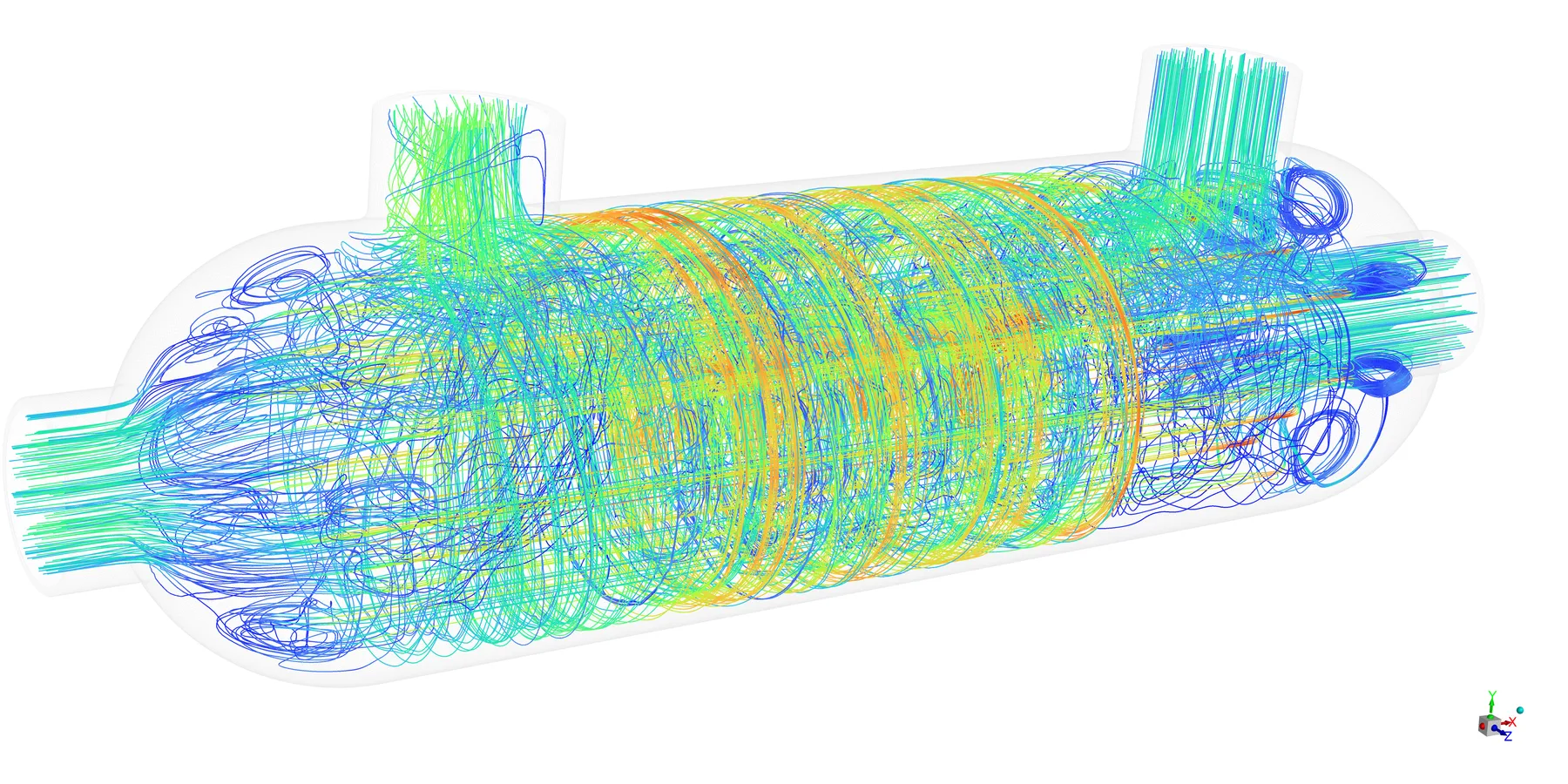
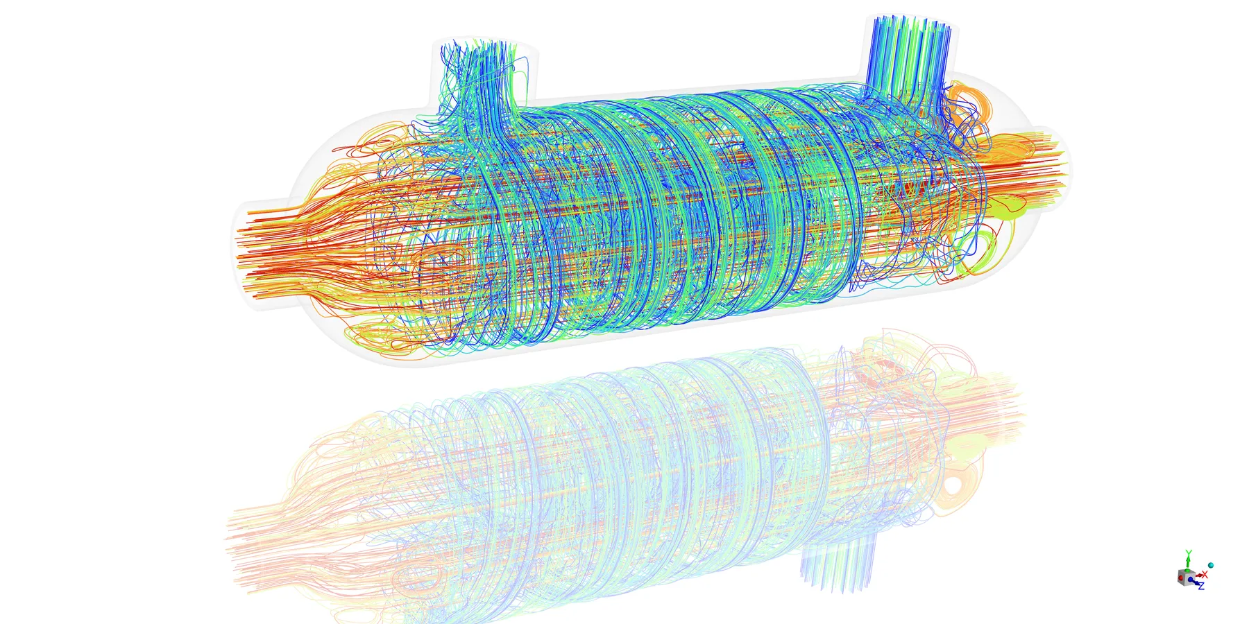
Flow distribution and thermal performance
Heat Exchanger Analysis
CFD can identify flow maldistribution, pressure loss, recirculation and temperature variations within heat exchangers and other thermal equipment.
Typical applications include:
- Flow distribution
- Heat transfer
- Temperature distribution
- Thermal performance
- Design optimization
- Troubleshooting existing equipment
What CFD can help you understand
Combustion & thermal systems
CFD can model complex combustion and thermal behaviour to support equipment design, troubleshooting and optimization.
- Burner and combustion performance
- Fuel-air mixing
- Flame behaviour
- Combustion temperature
- Emissions and pollutant formation
- Fired heaters and furnaces
- Thermal oxidizers
- Heat exchangers
- Spray cooling
- Conjugate heat transfer
Auryx has particular depth in combustion and burner behaviour, alongside broader experience in heat transfer and reacting flow.
Process & industrial flow
CFD can be used to understand how fluids move through process equipment and identify problems such as pressure loss, flow separation, recirculation or poor distribution.
- Separators and vessel internals
- Knock-out drums
- Reactor internals
- Catalyst beds
- Static mixers
- Piping and manifolds
- Flow distribution
- Pressure loss
- Multiphase flow
- Particle transport
- Free-surface flow
These applications are particularly relevant when evaluating equipment before fabrication or investigating performance problems on existing installations.
Offshore & marine CFD
CFD can be applied to offshore structures, marine systems and equipment exposed to complex fluid environments.
- Flow around offshore structures
- Wind and current interaction
- Hydrodynamic loading
- Aerodynamic loading
- Wave and free-surface interaction
- Sloshing
- Flow-induced loads
- Offshore ventilation
- Gas dispersion
- Subsea flow
- Flow assurance
- Fluid-structure interaction
For structural engineering questions, CFD can also provide pressure, thermal or flow-induced loading data for subsequent structural analysis.
Aerodynamics & environmental flow
CFD can be used to investigate airflow and aerodynamic behaviour around equipment, structures and industrial facilities.
- Aerodynamic performance
- Wind loading
- Flow around structures
- Flow-induced effects
- Ventilation
- Gas accumulation
- Smoke and gas dispersion
- HVAC performance
- Analyzer shelters
- Compressor enclosures
- Process buildings
These studies can help evaluate designs before construction, modification or field testing.
CFD for oil & gas operators
For oil & gas operators, CFD can provide engineering insight into equipment performance, operational problems and proposed modifications.
Typical applications include:
- — Burner and combustion analysis
- — Flare and vent dispersion
- — Gas accumulation and ventilation
- — Separator performance
- — Flow distribution
- — Heat exchanger performance
- — Existing equipment troubleshooting
- — Thermal problems
- — Flow-induced vibration
- — Design modification assessment
- — Offshore flow and loading studies
Auryx works with operators and other project stakeholders across the UAE, Saudi Arabia, Qatar and Oman, as well as Europe and North America.
CFD for OEMs & equipment manufacturers
For OEMs and equipment manufacturers, CFD can be used during product development, design validation and optimization.
Typical applications include:
- — Equipment development
- — Design comparison
- — Performance optimization
- — Burner and combustion development
- — Thermal management
- — Flow distribution
- — Pressure-drop analysis
- — Multiphase flow
- — Aerodynamic analysis
- — Hydrodynamic analysis
- — Design validation before fabrication
- — Investigation of field performance
CFD can help identify design issues before they become expensive fabrication or testing problems.
CFD for engineering and project development
CFD is often most valuable when it is integrated into a broader engineering decision.
Auryx combines CFD coordination with experience in technical specification, technology selection and vendor evaluation. This allows the CFD study to be framed around the actual project requirement and constraints rather than treating simulation as a standalone technical exercise.
Auryx Energy — CFD Framework
From engineering question to decision
We establish what the study needs to determine and which decision the results have to support.
Design options and operating scenarios are framed so the simulation answers a real choice.
Geometry, mesh, physics and boundary conditions are selected to suit the question being asked.
Findings are assessed against performance targets, specifications and project constraints.
The outcome is a clear recommendation that feeds directly into design, specification or supplier selection.
This approach is particularly useful where CFD results need to feed into equipment selection, design changes, specifications or investment decisions.
Flow physics and modelling approaches
CFD is not a single modelling method. The appropriate approach depends on the physics involved and the engineering question being investigated. Our CFD capability covers:
- Incompressible and compressible flow
- Laminar and turbulent flow
- RANS and DES turbulence modelling
- Steady-state and transient simulation
- Reacting flow
- Species transport
- Combustion chemistry
- Emissions and pollutant dispersion
- Multiphase flow
- Gas-liquid separation
- Free-surface flow
- Particle transport
- Conjugate heat transfer
- Fluid-structure interaction
The selection of mesh, turbulence model, boundary conditions and other modelling assumptions is documented and considered as part of the engineering study.
CFD, structural analysis & fluid-structure interaction
CFD and structural analysis can be combined when fluid behaviour affects mechanical integrity.
CFD can provide pressure, thermal or flow-induced loads that are subsequently used in finite element analysis (FEA). Coupled fluid-structure interaction can also be considered where the interaction between the fluid and structure itself is important.
- Offshore structures
- Flare tips
- Furnace tubes
- Thermowells
- Piping
- Flow-induced vibration
- Acoustic excitation
- Thermal loading
- Wind and aerodynamic loading
How a CFD study is built
- 1
Define the engineering question
The first step is to establish what the study needs to determine and what decision the results need to support.
- 2
Define the geometry and fluid domain
The relevant fluid domain is created from available CAD geometry, drawings or other equipment information.
- 3
Develop the computational mesh
The domain is divided into control volumes, with mesh refinement applied where greater resolution is required.
- 4
Define the physics and boundary conditions
The appropriate flow model, turbulence treatment, material properties, operating conditions and boundary conditions are established.
- 5
Run and assess the simulation
The governing equations are solved iteratively until the solution reaches an appropriate level of convergence. Mesh quality, model selection and boundary conditions all influence the reliability of the result.
- 6
Interpret the results
Results can be presented through contours, streamlines and quantified values throughout the domain. The important step is connecting those results back to the original engineering question.
- 7
Translate results into recommendations
The final output should make clear what the simulation means for the design, equipment or operation, and what action should follow.
What you receive
A typical CFD study includes:
- — CFD report structured around the original engineering question
- — Flow, temperature or concentration visualizations
- — Quantified findings
- — Relevant design comparisons
- — Engineering interpretation
- — Practical recommendations
- — Review session with your engineering team
Typical study duration is approximately two to eight weeks, depending on complexity. Steady-state single-phase studies generally sit toward the shorter end, while transient combustion and multiphase studies typically require more time.
Studies can be performed remotely, with online review meetings. Site visits can also be arranged where existing equipment and field data are relevant to the analysis.
Why work with Auryx Energy?
Independent coordination
Auryx provides independent CFD support rather than tying the analysis to a particular equipment supplier or technology.
Engineering-led scope
The study starts with the engineering question and the decision that needs to be made.
Technical and commercial perspective
Our experience in technical specifications, procurement and vendor evaluation helps connect simulation results with the wider project context.
Practical output
The objective is not simply to produce CFD plots. Results are interpreted and translated into findings and recommendations that your team can use.
International delivery
Projects can be coordinated remotely for clients in the Middle East, Netherlands, Europe and North America.
Industries & applications
Our strongest experience is within the energy and process industries, including:
Oil & Gas
Gas processing, refining, sulphur recovery, storage, loading systems, flares, process equipment and offshore applications.
Power Generation
Combustion systems, HRSG and boiler flow distribution, stack dispersion and thermal applications.
Petrochemical
Reactor internals, furnace performance, mixing, quench systems and process flow.
Renewables & Biogas
Digester mixing, gas upgrading equipment and flare systems.
Offshore
Separator behaviour, flow assurance, ventilation, dispersion, hydrodynamic and aerodynamic applications.
The underlying CFD methods extend across these sectors because the same fundamental flow, heat-transfer and fluid-interaction physics apply in different engineering environments.
Frequently asked questions
What information is needed to start a CFD study?
Typically, we need geometry such as drawings, 3D models or equipment datasheets, together with the operating conditions and a clear definition of the engineering question. Where information is incomplete, assumptions can be established during scoping.
How long does a CFD study take?
Most studies take approximately two to eight weeks from kickoff to final report, depending on complexity and the type of simulation required.
How accurate is CFD?
Accuracy depends on factors including mesh quality, model selection and the quality of the boundary conditions. Where field or test data is available, it can be used for validation. Expected accuracy and limitations should be stated openly for the specific study.
What is the difference between steady-state and transient CFD?
A steady-state study resolves the time-averaged flow and is suitable for relatively stable operating conditions. Transient CFD resolves behaviour over time and is required for phenomena such as flame dynamics, sloshing, pulsation, start-up or upset scenarios.
Can CFD be combined with FEA?
Yes. CFD results can be coupled with finite element analysis where fluid pressures, thermal loads or flow-induced effects influence structural integrity.
Can CFD studies be performed remotely?
Yes. Studies can be scoped, executed and delivered remotely, with online technical reviews. Site visits can be arranged where field information would strengthen the analysis.
Middle East, Netherlands and international projects
Auryx Energy supports oil & gas operators, EPC contractors, OEMs and technology providers in the Middle East, with a particular focus on the UAE, Saudi Arabia, Qatar and Oman.
We also support clients in the Netherlands, Europe and North America, delivering CFD studies remotely wherever the project is located.
Need CFD support for a specific engineering problem?
Whether you are evaluating a new equipment design, investigating an operational problem, assessing a modification or need specialist CFD capability for an offshore or industrial application, we can help define the appropriate study.
Independent advice. Practical results.